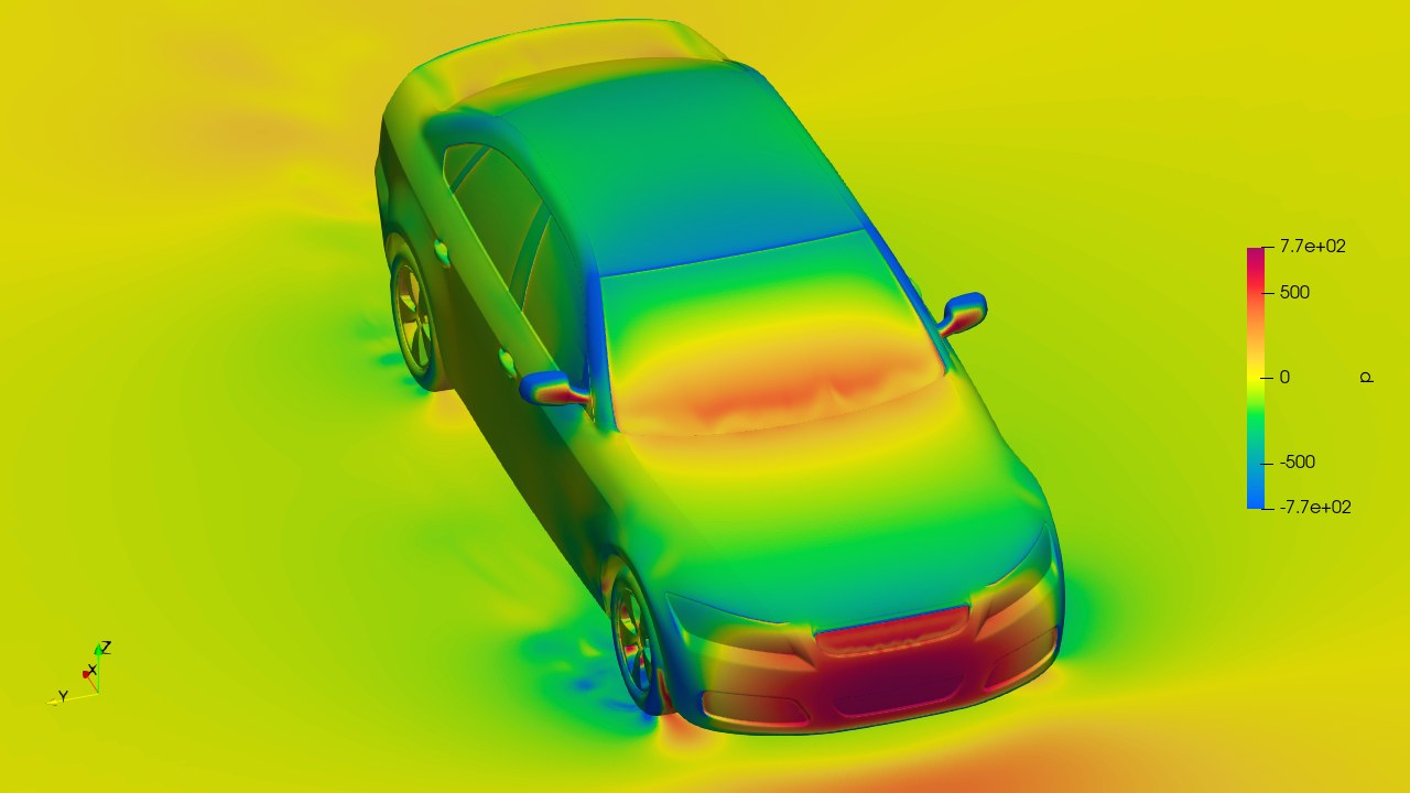
The OpenFOAM HPC Challenge was launched by the OpenFOAM HPC Technical Committee to take a snapshot of how OpenFOAM performs on current production hardware, and how much software optimisations can add to it. All participants run the same industrial case. The challenge is held every year since 2025, and Wikki GmbH is one of its organisers.
The results of the first challenge, OHC-1, were presented in a mini-symposium at the 20th OpenFOAM Workshop in Vienna on 1 July 2025. Sergey Lesnik of Wikki was a member of the organising committee and analysed and presented the results together with Gregor Olenik (TUM) and Mark Wasserman (Huawei). The rest of this page describes OHC-1.
Highlights of OHC-1
- 237 valid data points from 12 organisations in academia, research centres and industry.
- 25 CPU models from AMD, Intel and ARM and 3 GPU models, from a single node up to 256 nodes (32,768 CPU cores).
- Time to solution from 7.8 minutes to 65.7 hours, energy to solution (where reported) from 2.1 to 236.9 kWh.
- On-package high-bandwidth memory (HBM) gives the best single-node performance.
- Software optimisations reached up to 28 % lower energy per iteration, 17 % higher maximum throughput and 72 % shorter time per iteration than the best hardware-track results.
- Wikki’s custom mesh partitioner and tuned settings made the solver up to 2 times faster.
The case
The challenge case is the external aerodynamics of the DrivAer car model with closed cooling inlets and static wheels (occDrivAer): a full car with engine bay, cooling channels and a complex underbody. A similar configuration was studied in the Automotive CFD Prediction Workshops (AutoCFD2 to AutoCFD4), so reference results were available. It was computed as a steady-state, incompressible RANS simulation with the k-ω SST turbulence model and simpleFoam, on three meshes of 65, 110 and 236 million cells created with snappyHexMesh. The case is available in the repository of the HPC Technical Committee, based on a setup provided by Upstream CFD.
Two tracks
- Hardware track: the prescribed setup with the official OpenFOAM v2412 release. Only the hardware, the number of nodes and cores and the system software could vary.
- Software track: any OpenFOAM version, custom solvers and code changes, as long as the mesh and the physical model stayed the same. The drag, lift and side-force coefficients had to be statistically converged within a prescribed limit and were compared with reference results.
The submissions were compared by time to solution, energy to solution, time and energy per iteration and FVOPS (finite-volume operations per second: cells × iterations / wall-clock time). FVOPS is a throughput metric that allows runs on different meshes and machines to be compared.
Hardware track
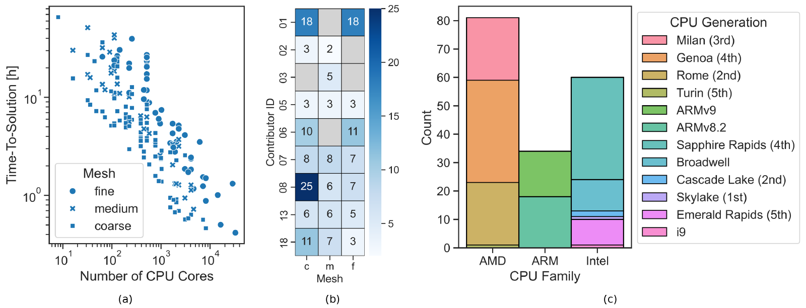
The hardware track received 175 runs. All three meshes were well covered: most runs used the coarse mesh and the fewest the medium mesh, as participants concentrated either on single-node performance or on extreme scaling. Of the runs, 81 used AMD, 60 Intel and 34 ARM CPUs of several generations.
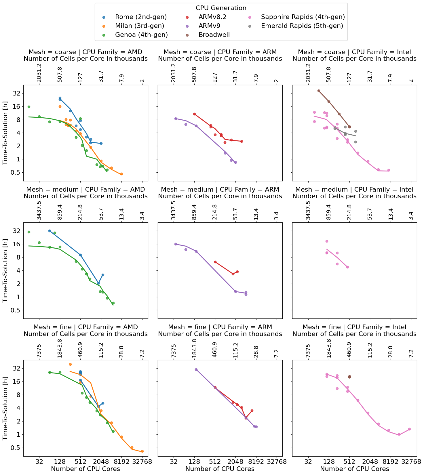
The strong-scaling plots run the same mesh on more and more cores. Time to solution falls with the core count for all CPU families and meshes, but no configuration scales ideally over the whole range. Within a node, the cores compete for memory bandwidth. Across nodes, communication takes over, because OpenFOAM parallelises with MPI only and the share of communication grows as the subdomains shrink. Some curves even rise again at high core counts, typically between 10,000 and 50,000 cells per core; a practical limit of about 10,000 cells per core was observed. Within each CPU family, newer generations are generally faster at the same core count.
The manuscript also shows the trade-off between time and energy to solution. Its Pareto front shows that a moderate increase in energy buys a large reduction in run time, while beyond that point more nodes save little time at a high energy cost. On a single node, CPUs with on-package high-bandwidth memory give the fastest and most energy-efficient runs, because OpenFOAM’s sparse solvers are limited by memory bandwidth.
Software track
Five organisations submitted 62 software-track runs: full GPU ports (Engys, CINECA), offloading of the linear solvers to GPUs (KIT/TUM), optimised decomposition (Wikki, KIT/TUM), mixed precision and selective memory allocation (Huawei) and the coherent I/O format (Wikki). Selective memory allocation lowered the energy per iteration from 2,613 to 1,867 J. GPU ports reached the highest throughput per node and needed 10 to 15 times fewer nodes for comparable peak performance, but scaled less well; the highest total throughput came from optimised decomposition on CPUs. A key result: optimised software on older hardware can beat the unoptimised code on the newest CPUs.
Wikki’s contributions
- Custom mesh partitioner. Profiling showed long delays for partitions with many boundaries to other nodes, where communication is about ten times slower than within a node. Wikki wrote a new partitioner that places the partitions near the node boundaries so that the number of messages between nodes is minimised. Together with tuned solver settings it made the solver 1.45 to 2.01 times faster on the 65- and 236-million-cell meshes with 1,024 to 8,192 partitions; the partitioner accounts for about 75 % of the gain.
- Coherent I/O format. Pre-processing (decomposition, renumbering, initialisation) took up to eight times longer than the solver run itself. With the coherent format from the exaFOAM project, it was up to 20 times faster than with the collated format on the LUMI supercomputer.
Data and publication
All submissions (CC BY 4.0), analysis notebooks and presentations are open in the OHC-1 repository and archived on Zenodo (doi:10.5281/zenodo.17063427). An interactive notebook allows custom analyses of the full data set.
- S. Lesnik, G. Olenik, M. Wasserman: The First OpenFOAM HPC Challenge (OHC-1). Manuscript, arXiv:2603.27565, 2026.